

courtesy of Forum member Purge (David Blair)
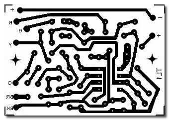
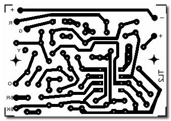
Similarities
There are a lot of similarities between the Thunder PCB foil patterns:
Guitar version 1

Guitar version 2

Bass

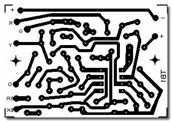
The second version foil pattern can be used for all 3 circuits.
The only differences between the 3 are highlighted below:
Differences

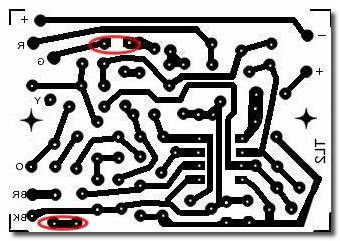
The pads highlighted at the bottom are used for the guitar version 2 and bass versions.
They may be left on and just not used for the first version.
The top highlight shows the tracks for the first and second versions.
These two pads are linked for the bass circuit.
Use version two for both one and two, for version one ignore the two highlighted at the bottom.
For the bass version put a wire link across the two pads highlighted at the top.
Tips
All the voltage ratings for polarised capacitors are just what Matsumoko originally used.
The rating is not critical, anything over the power supply voltage will work.
Increased battery life
On Thunders there is a diode in the supply path.
I can only think this is for accidental reverse polarity protection, which can’t happen.
To get reverse polarity you would have to deliberately hold both batteries on the wrong way round.
There is a drop of about 1V across the diode, batteries will last longer if it is removed or bypassed.
Battery connector broken?
Bypass it, the Thunder circuits will run off one battery.
Component orientation
On the original circuits most of the resistors are oriented the same way.
That makes it easy to accidentally short two resistors together.
If you’re making your own Thunder circuit I recommend alternating the orientation to prevent this.
Myths
Headroom
More a misconception than a myth. Does an 18V supply to the circuit gives more headroom than 9V?
Yes but in this case it makes no practical or audible difference.
Headroom is essentially the amount by which the input signal can be increased before clipping distortion occurs.
The opamps used can take an input equal to the supply voltage and the input signal from the pickup is probably no more than 100mV giving massive amounts of headroom. (Way more than will ever be needed)
An 18v supply just gives even more massive amounts of headroom than 9v.
An 18V supply is more economical than a 9V supply
The circuit will work off a supply voltage between 3V and 30V but due to the diode 1V voltage drop the minimum battery voltage is 4V.
One battery – maximum voltage drop is 5V (9V to 4V)
Two batteries – maximum voltage drop is 14V (18V to 4V), nearly three times more.
3 batteries would last comparatively longer, but that’s probably overkill.
PCB making
All the PCB foil patterns featured here are mirrored as I use the photo paper method to make PCBs.
- Print the foil pattern on photo paper using a laser printer – inkjet printers won’t work for this
- Using a hot iron, iron the pattern onto your blank PCB material
- Let it cool then soak in warm water and gently use a fingernail to remove the backing paper
- The pattern is now on the PCB ready for etching
- Once etched use a dish scouring pad to gently remove the printer toner.
There are other methods and many tutorials on YouTube, this is just the one I prefer.