

The following information is for circuits on all Thunder basses
courtesy of Forum member Purge (David Blair)
Printed Circuit Board Assembly
click to enlarge

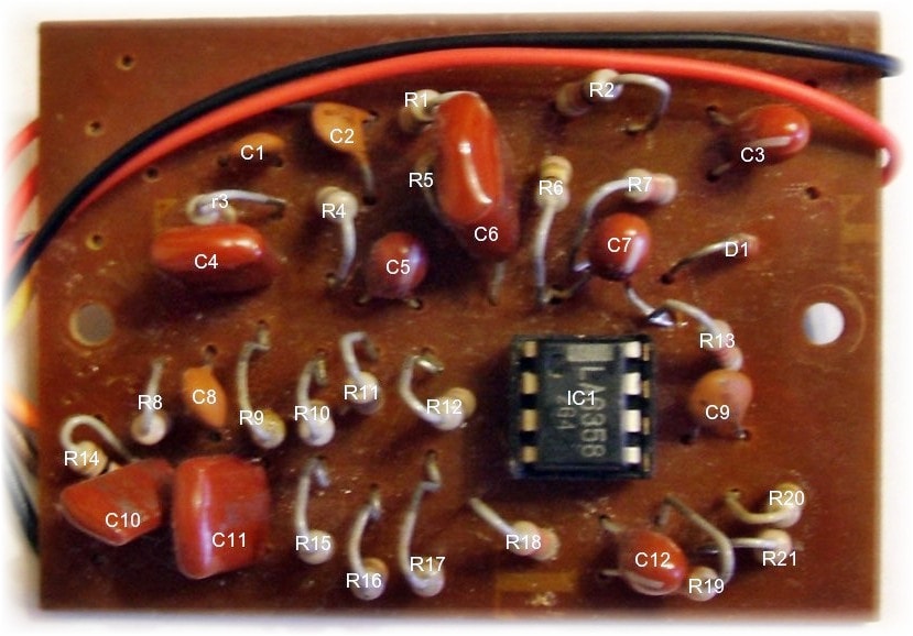
Components identification
RESISTORS – all 0.25W 10% tolerance
R1 100k
R2 1k
R3 2.2m
R4 1m
R5 68k
R6 100k
R7 22k
R8 330k
R9 47k
R10 100k
R11 68k
R12 100k
R13 22k
R14 10k
R15 100k
R16 220k
R17 27k
R18 22k
R19 22k
R20 560k
R21 1m
CAPACITORS
C1 470pF ceramic
C2 470pF ceramic
C3 4.7uF 35v tantalum
C4 47nF Mylar
C5 4.7uF 35v tantalum
C6 68nF Mylar
C7 4.7uF 35v tantalum
C8 220pF ceramic
C9 220pF ceramic
C10 10nF Mylar
C11 47nF Mylar
C12 4.7uF 35v tantalum
semiconductors
IC1 LA6358 (Obsolete – use LM358)
D1 – small signal diode, probably 1N4148
Click Here for connection details to the pots and switches on a Thunder IA bass or HERE for Thunder IIA and Thunder III model
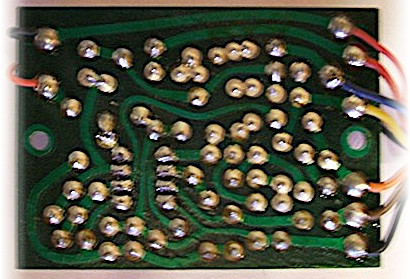
Printed Circuit Board—bottom
Printed Circuit Board—foil pattern | mirrored
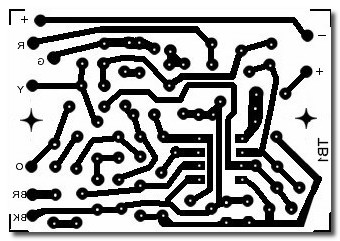
CLICK HERE for more information on PCB making